No. 03 · Business · 2021
Aozora PCB
The printed circuit board inside the Aozora 69, laid out in KiCad around the ways keyboards actually die: worn traces under the stabilizers, torn USB pads, and noisy clocks.
- Role
- PCB layout
- Tool
- KiCad
- Controller
- ATmega32U4
In this issue
- (1)A PCB built not to fail
- (2)Routing that dodges the failure points
- (3)A USB port that can’t tear off
- (4)A clock placed for stability
Aozora PCB · Hardware design
Part of SalmonCat Studios. The board everything on the Aozora sits on: 68 hotswap sockets and a USB-native controller, routed so nothing wears through.
A PCB built not to fail
A low price usually signals corners cut on the part nobody photographs: the PCB. We went the other way. I laid out the board to survive the abuse that quietly kills keyboards costing twice as much.
The shipping layout, both copper layers
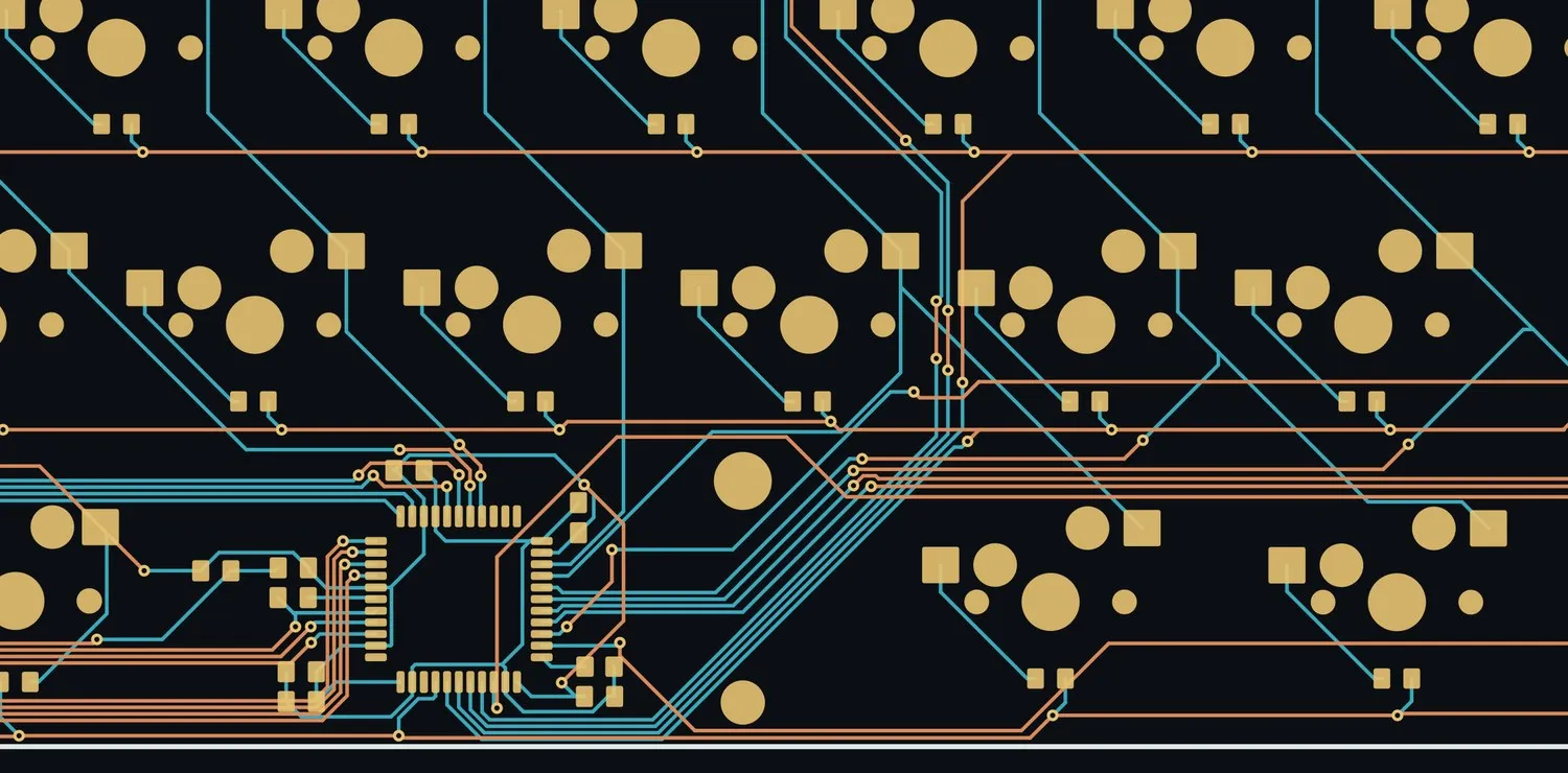
68 hotswap sockets, 69 per-key diodes, the ATmega32U4 and its 16 MHz crystal, and a USB-C port. Front copper in amber, back copper in teal.
Rendered from the shipping aozora_PCBv1 KiCad file.
The shipping file, aozora_PCBv1, routes 1,108 track segments through 140 vias across 112 nets. Most of the key matrix runs on the back layer, which keeps the front clear around the controller. Switch between the layers above to see the two halves of the job.
Routing that dodges the failure points
On a lot of boards, the Drop / Massdrop K-Type I used to own among them, matrix traces run right under the stabilizers and stab wires. Years of flex and friction abrade the copper until a key silently dies. I routed the matrix clear of every stabilizer cut-out and moving part, so no trace sits where the mechanism can wear it through.
The five stabilizer positions, on the back copper
Where most of the matrix runs, with every stabilizer marked.
- 1Stabilizers Backspace, Enter, both Shifts and the spacebar. No matrix trace runs where a stabilizer wire moves.
Rendered from the shipping aozora_PCBv1 KiCad file.
A USB port that can’t tear off
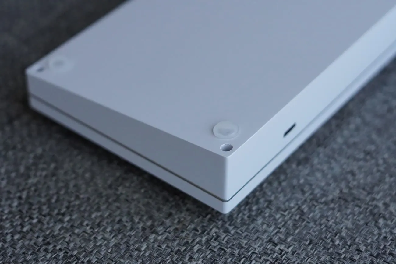
The most common way a keyboard dies is the USB connector ripping its pads off the board. I placed the Type-C port to seat tightly into the milled case, so the aluminium housing, not the solder joints, takes the strain of every plug and unplug.
A clock placed for stability
The 16 MHz crystal and its passives were chosen and positioned for long-term stability. High-speed lines were kept short and terminated, and the crystal placed with its harmonics in mind, so the board never turns its own traces into stray antennas: RF discipline you rarely see at this price.
Where the parts sit
The front copper, with the port, controller and crystal marked.
- 1USB-C port Seated so the milled case takes the strain of every plug and unplug.
- 2ATmega32U4 USB-native controller, with series-terminated data lines and decoupling on every rail.
- 316 MHz crystal Kept close to the controller on short, deliberate traces.
Rendered from the shipping aozora_PCBv1 KiCad file.
The board at a glance
- MCU
- ATmega32U4 · USB-native, VIA-flashable
- Clock
- 16 MHz Seiko-Epson crystal · 22 pF loads
- Connector
- HRO USB Type-C
- Switches
- 68× Kailh hotswap sockets
- Matrix
- 69× 1N4148 per-key diodes · full N-key rollover
- Integrity
- 22 Ω series USB lines · 0.1 µF decoupling per rail